Project Editor
You use the Project Editor to create or modify a project, add files to your project (such as timing constraint files), and choose a device family and device. To create a new project, choose or click the Create Project icon.
Project Tab
- Linux—/home/<user name>/.efinity
- Windows—C:\Users\<user name>\.efinity

Design Tab
Use the Design tab to add design and constraint files to your project. In Efinity® software 2024.2 and higher, you must specify a name for the Top Module/Entity. For new projects, the Top Module/Entity name defaults to the project name. You can edit the Top Module/Entity name without changing the project name.
For existing projects, changing the project name does not automatically update the Top Module/Entity name. Therefore, if you want to change the top module or entity name, you must edit it in .

You can choose the top-level VHDL architecture, if desired.
You can set the default Verilog HDL, SystemVerilog, or VHDL version for the design files.
In Efinity® v2020.2 and higher, you can define VHDL libraries and add files to them. See Using VHDL Libraries for details.
- Turn on Copy to Project to copy the imported files to your project directory. You can choose whether to flatten (copy all files to project root directory) or preserve the directory structure.
- If you do not copy the files to your project, specify whether to reference the files as full or relative paths.
- Choose to import only design files or all files (which includes constraints).
Synthesis Tab
Optional. The Efinity® software supports options to help you direct the synthesis flow. Use the options on this tab to specify project-specific preferences. If you do not make any settings, the tool uses the defaults.

| Setting | Description |
|---|---|
| Work Directory | Specify a custom directory or use the default (work_syn). |
| Generate post synthesis netlist | Choose whether the software should create this netlist. Default:
On |
| Synthesis Options |
See "Synthesis Options" in the .Efinity Synthesis User Guide
|
| Include Dir | Specify directories to include in your project. If you use the IP Manager to add IP, the ip/<module> directory is listed here. The software searches these locations when you use include statements. |
| Dynamic Parameter | Use this area to add parameters and values that apply to the top-level module or entity in your project. The value passed into the Dynamic Parameter field must be the same format as that you would use for any variable in VHDL or Verilog HDL. For example, string should be in quotation marks. |
| Verilog `define Macro | Use this area to add `define macros to your project. Some FPGA
EDA tools automatically create a SYNTHESIS macro. If you want to use
the same behavior in the Efinity software, you need
to create it here. For example, click the Add Verilog `define Macro
button and then enter SYNTHESIS in the
NAME field and 1 in the
Value field. Then if you want to include
simulation only code, use this format:You can also use the translate_on and translate_off
directives to accomplish similar functionality. |
Place and Route Tab
- The optimization levels (
--optimization_level) are settings that control both placement and routing, targeting different metrics.- CONGESTION optimization levels may help a congested design meet timing.
- TIMING optimization levels may help a non-congested design meet timing requirements.
- POWER optimization levels may help reduce a design’s power consumption.
- The placer effort level (
--placer_effort_level) is a way to control how much runtime the placer uses when it tries to improve placement quality. - The number of threads (
--max-threads) controls how many thread that the placer can launch. The default setting (-1) means that the placer uses the maximum number of available processors. - The
message suppression options (
--suppress_info_msgs,--suppress_warning_msgs, and--msg_suppression_list) suppress INFO and WARNING messsages from place and route. - The
--seedoption introduces random noise in the placer. The seed is the value you set.

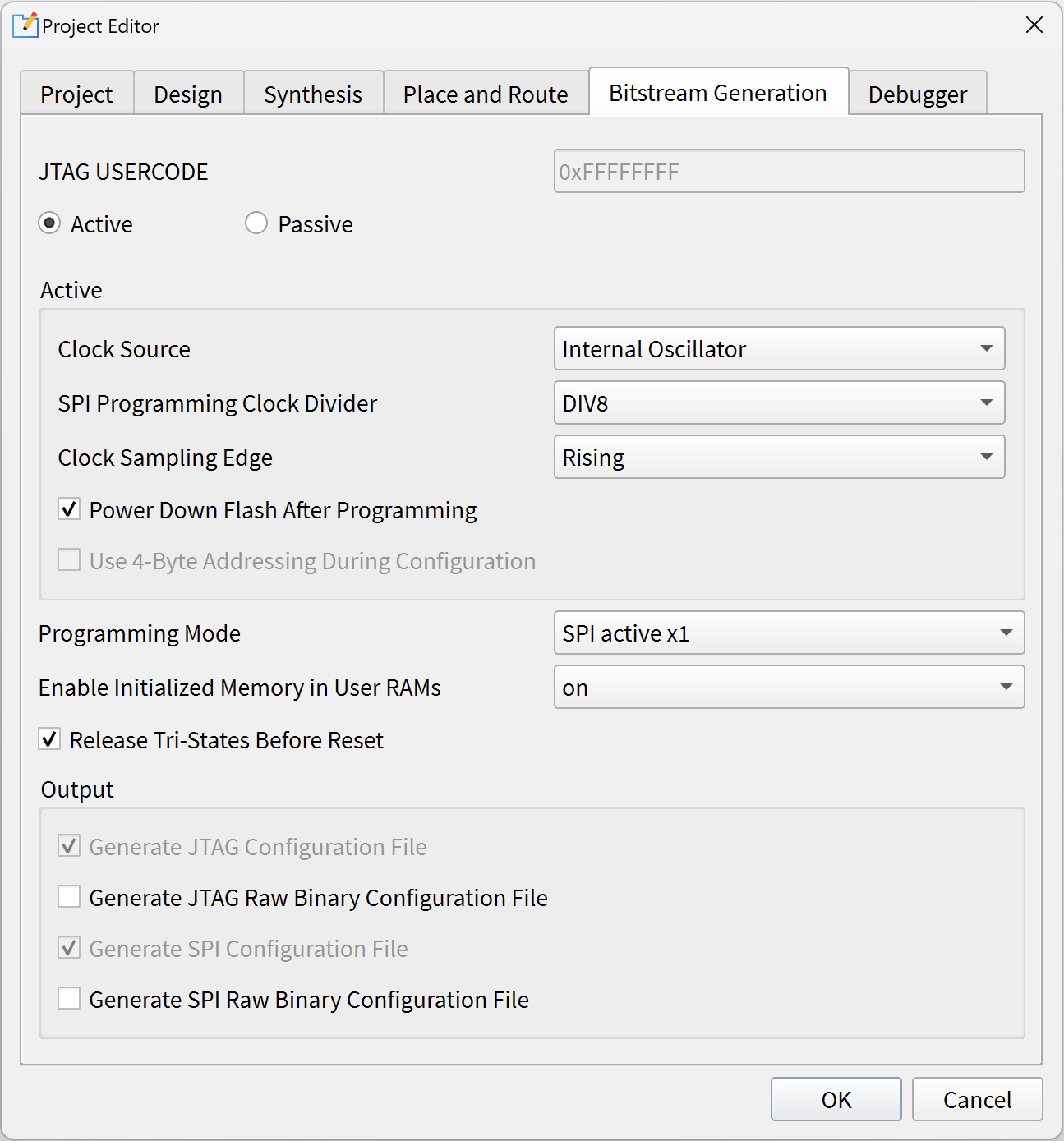
Bitstream Generation Tab
Optional. Use the options on this tab to specify project-specific preferences such as the programming mode, daisy chaining, and memory initialization. If you do not make any settings, the tool defaults to SPI active programming mode.
Debugger Tab
Optional. This tab is where you enable or disable a debug profile to auto-instantiate in your design and set a working directory for debugging. These settings are used with the Debug Wizard.
