Using the Fractional PLL Block
Titanium FPGA's PLL block lets you configure the reference clock, feedback options, frequency, and output clocks for the PLL. You set up the PLL using the PLL Clock Calculator, which provides an easy-to-use graphical way to specify the frequencies and other settings.
- In the PLL's Properties tab, you specify general settings such as the instance name, PLL resource, clock source, and external clock.
- You can invert any of the clock outputs by clicking Inverted for the clock output in the Output Clock Inversion box.
- Clock outputs 3 and 4 can feed the global or regional clock network. Choose gclk (default)) or rclk under Connection Type.
- Click the Automated Clock Calculation button to open the PLL Clock Calculator.
Reference Clock Settings
The PLL has four possible reference clocks. Depending on the PLL, one or two of the clocks can come from the FPGA core, and two or three can come from off chip. You select the clocks using the Clock Source drop-down box:
- core—The PLL reference clock comes from the FPGA core.
- external—Enables clock 0 or 1. The PLL reference
clock comes from an external pin. The GUI displays the resource(s) that can
be the reference clock.Note: In this mode, a GPIO block with a pll_clkin connection type must generate the reference clock(s). The software displays which resource(s) you can use (and the instance name if you have created it).
- Add a GPIO block.
- Enter the instance name.
- Choose input as the mode.
- Choose pll_clkin as the connection type.
- In the Resource Assigner, assign it to the resource shown in the PLL's Properties tab.
- dynamic—Enables all four clocks; requires a clock selector bus to choose the clock dynamically. The GUI displays the resource(s) that can be the reference clock.
Advance Setting Tab: SSC
The fractional PLL supports spread-spectrum clocking. The available modes are:
- Disable—Turn off spread-spectrum clocking.
- Static—Always use spread-spectrum clocking.
- Dynamic—Only use spread-spectrum clocking when activated by an enable signal.
| Parameter | Choices | Description |
|---|---|---|
| SSC Modulation Frequency (KHz) | User defined | Enter the frequency. |
| SSC Modulation Amplitude (%) | User defined | Enter the amplitude. |
| SSC Spread Direction | Up, Down (default), Center | Indicate how the spectrum is applied to the waveform. |
| User SSC Enable Pin Name | User defined | Indicate the enable pin name. Dynamic mode
only. |
Advance Setting Tab: Dynamic Reconfiguration
The fractional PLL supports a dynamic reconfiguration mode, which lets you change the PLL setting on the fly after initial boot-up without having to re-configure the FPGA. Turn on Enable to use this feature.
You need to enable the reset and lock signals !!!
Efinix provides the PLL Dynamic Reconfiguration core and the PLL Dynamic Reconfiguration Wizard to help you integrate this feature in your design.
| Parameter | Choices | Description |
|---|---|---|
| Enable | On, off | Turn on to enable dynamic reconfiguration. |
| Reference Clock Selector [1:0] Bus Name | User defined | Specify the bus name for the reference clock selector. |
| [2] Core Clock 0 Name | User defined | Specify the core clock name. |
| [3] Core Clock 1 Name | User defined | Specify the core clock name. |
| Configuration Clock Pin Name | User defined | Specify the configuration clock name. |
| Configuration Data Output Pin Name | User defined | Specify the configuration data output name. |
| Configuration Select Pin Name | User defined | Specify the configuration select name. |
| Reconfiguration Wizard | – | Click to open the wizard. |
The PLL Dynamic Reconfiguration Wizard helps you define one or more PLL configuration sets that you use later to dynamically change the PLL's comfiguration.
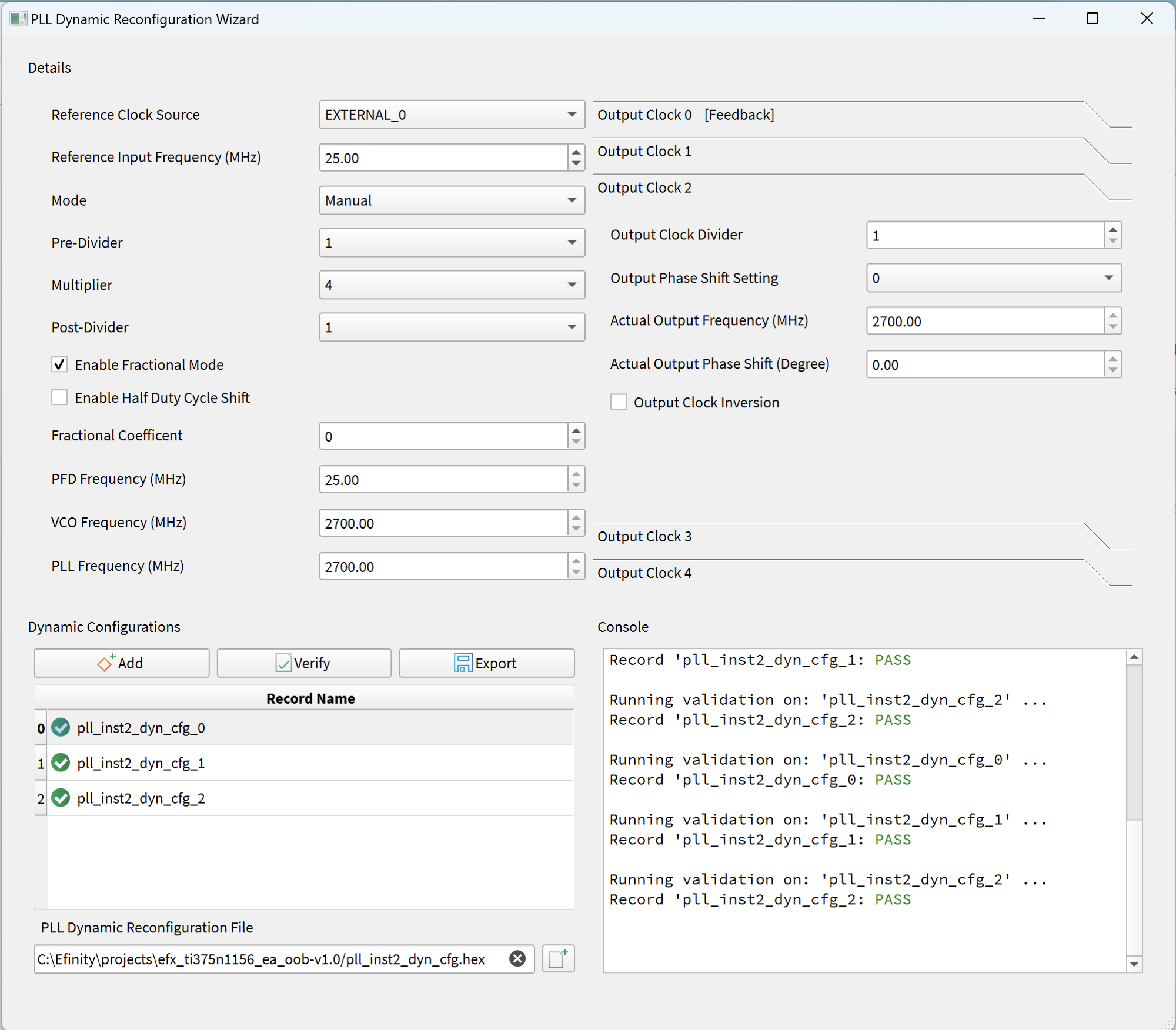
- Click Add to create a new configuration set.
- Enter the PLL settings. Because the settings are complicated, Efinix suggests that you create a configuration first using the PLL Clock Calculator, note the resulting settings, and then enter them into the wizard.
- Click Verify. The wizard checks your settings to make sure they are legal values. The results display in the Console.
- Specify the output file name (.hex) in the PLL Dynamic Reconfiguration File box or use the default.
- Click Export to save your configuration settings to the .hex file. Make note of the name; you specify this .hex file when you configure the PLL Dynamic Reconfiguration core.